Instrumental Ultraviolet and Visible spectroscopy
- HOME Email Webmaster
Related Links :
- Graphite Furnace AAS
- Spectral interferences
- Infrared spectroscopy
- Hg/cold vapor and As/hydride
- Atomic absorption spectroscopy
uv vis instrumentation
Different substances absorb different wavelengths of light. The wavelength range associated with the uv-vis range is between 200 and 800nm of the electromagnetic spectrum. This range deals with the excitation of electrons that jump from lower levels to higher levels and absorb light of only a specific wavelength.
SINGLE BEAM DESIGN
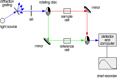
A light source is directed into a diffraction grating of the monochromator and a specific wavelength is selected and passed through the sample. A detector analyses the intensity of light reaching it and the amount passed through the sample, and processes this information to give an absorbance.DOUBLE BEAM SYSTEM
In a simple double beam instrument the light path is alternately directed by a rotating chopper mirror as it passes in and out of the sample and reference
When light passes through the sample the detector measures P and when the chopper diverts the beam through the reference the detector measures P0
The beam is chopped several times repeatedly and the computer electronics automatically compares P and P0 to calculate Absorbance and Transmittance.
Components that make up the uv vis spectrophotometer
In relation to the components shown in the Table, different combinations of light sources, monochromators, and detector systems can be assembled and integrated to make up a spectrophotometer for other applications and wavelength suitability.
Radiation source Optical system Detector sample Deuterium lamp
Hydrogen lamp
Tungsten halogen
Xenon discharge
Tungsten filament
Mercury vapor
CarbononeMonochromator
Polychromator
Entrance slit
Collimating lens
Prism
Grating
Focusing lens
Exit slit
Photomultiplier
Photovoltaic cell
Photodiode
Photocell
Phototube
CCD(charged-couple)
Diode arrayQuartz
Fused silica
Glass
Polythene
Path lengthA spectrophotometer will only consist of the component parts that make up the instrument. The one that is configured here is the Double Beam UV-VIS full spectrum scanning spectrophotometer using a Deuterium and Tungsten lamp as radiation source, a Grating monochromater as wavelength selector, and a Photomultiplier tube as the Detector.
Light source
To get a light source to cover the entire UV and Visible range, a combination of two lamps have to be used, a deuterium lamp for the 190 400 nm part of the UV spectrum, and a tungsten lamp 350 2500 nm for the visible part. These lamp wavelengths will overlap into the near UV and the near IR spectral regions, which is close to the visible region on both sides of the spectrum.
Deuterium Lamp
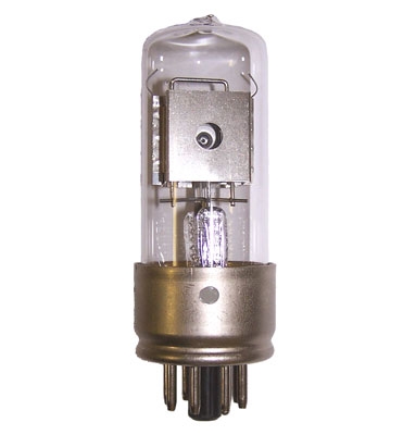
A deuterium lamp has a tungsten filament and a Ni plate anode filled with deuterium gas under low pressure. When subjected to a high voltage it produces a continuous spectrum in the UV region due to formation of excited molecular species. It emits radiation in the range of 160 375 nm. The lamp envelope is made of optical grade silica or quartz and exhibits excellent ultraviolet transmissions.
An arc is struck between the anode and cathode. The cathode is first heated and begins to emit electrons. A high voltage is then applied across the electrodes and the arc is established. This produces enough heat to excite molecular deuterium and main continuous emission. The heating current can then be switched off. The striking process takes a few seconds and emission is carried on automatically as a stable and uniform output.
Tungsten Filament Lamp
This is the conventional incandescent lamp. The spectral output is black-body radiation and wavelength range is about 350 3000 nm. The bulb is constructed of glass and the wavelength and intensity depends on temperature.
An inexpensive, stable light intensity can be obtained with a simple power supply However, the glass bulb darkens because of evaporation of tungsten from the filament. This results in loss of energy, noisey display and eventually, complete lamp failure.
Tungsten Halogen Lamp
The Tungsten Halogen lamp is the most commonly used source for Visible radiation. It emits continuous radiation in the range 325 3000 nm. This lamp is used in preference to the Tungsten Filament lamp due to the addition of a halogen into the envelope of the bulb.
The lamp has a tungsten filament which produces radiation when heated to incandescence by an electric current. The filament is housed in a quartz bulb containing a low pressure argon gas with a small amount of iodine added to improve the intensity.
It has a more compact tungsten filament with a quartz envelope and operates at a higher filament temperature. The lamp casing does not darken because the evaporated tungsten reacts with the iodine to form a volatile halide which on contact with the hot filament decomposes again and deposit the tungsten back onto the filament.
Monochromator
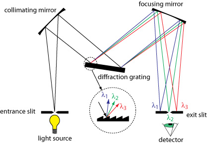
The most important design feature of the instrument is the monochromator and its purpose is to resolve polychromatic radiation into individual wavelengths.
It consists of an entrance slit to accommodate the source radiation and mirrors to pass the light through the system. It also comprises a dispersing element known as a Prism or Grating to spread the radiation into its constituent wavelengths and an exit slit to select the desired wavelength.
PrismSource light is collimated and reflected onto a prism and reflected back through the prism. It reflects light at the surface of two interfaces creating angular dispersion. The degree of dispersion depends upon the optical angle of the prism (usually 600) and the prism material which is optical glass.
Prisms have a non-linear dispersion and it is difficult to focus a desired wavelength through the exit slit. There is an inverse relationship between wavelength and dispersion, and shorter wavelength have greater spread. Light of one wavelength will be dispersed from the light of any other wavelength.
Diffration Grating
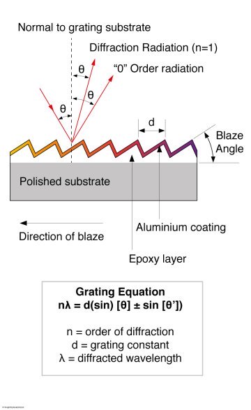
A Diffraction grating is an optical component integrated into the monochromator and is produced by physically creating grooves on a reflective surfacewith a diamond ruling (cutting) tool. Diffraction grating grooves cab etched on substrates such as glass, metal or ceramic. Gratings used in spectrophotometers are plastic replicas of high quality glass or metal master gratings.
When light transmits through or reflects off a grating, the grooves cause the light to diffract, dispersing the light into its component wavelengths. Radiation of only a specific wavelength is allowed to leave the monochromater through the exit slit, so that its intensity can be measured as a function of wavelength.
Holographic Grating
A layer of photoresist is sprayed onto a glass blank and exposed to an interference pattern produced by a high powered laser interferometer. The blank is thus developed with accurately parallel grooves corresponding to the imposed interference pattern. The unexposed region on the substrate is then etched away chemically by selective dissolution, and is treated with aluminium to form a master reflection diffraction grating. Copies can then be made as required or sufficient masters can be produced to fit originals in instruments as master blazed holographic gratings.
Detectors
Photomultiplier
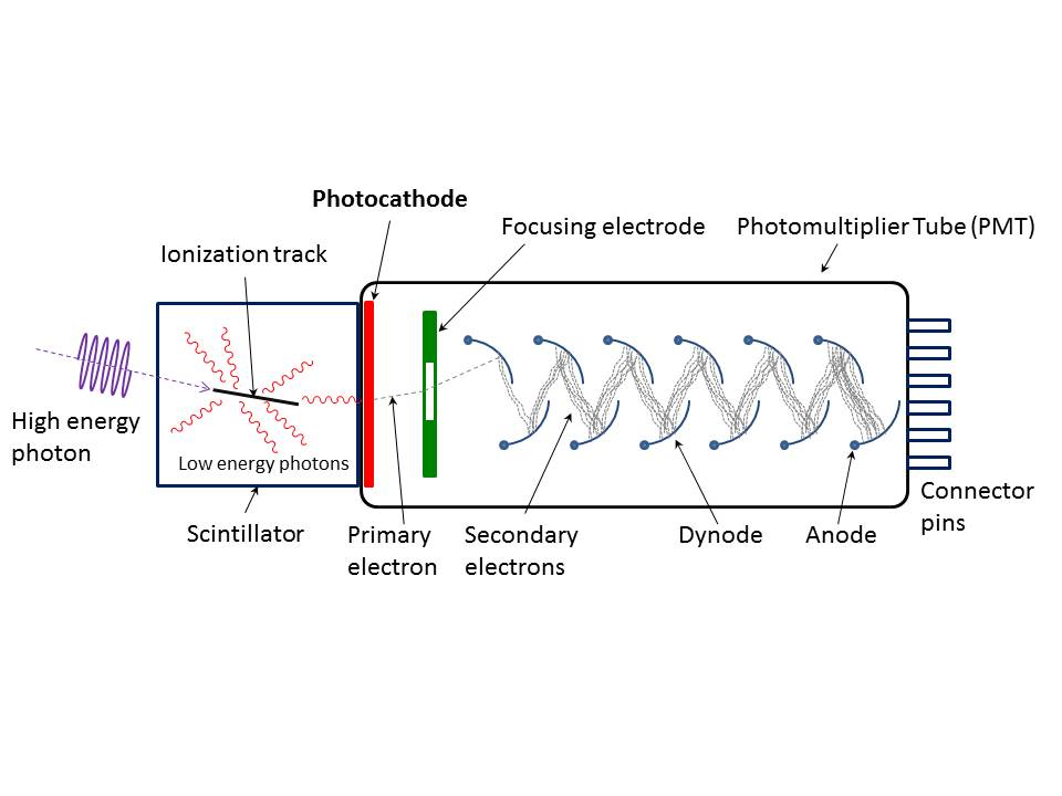
The purpose of a detector is convert radiant energy received into an electrical signal which can be multiplied and measured as a flowing current. The photomultiplier is an evacuated glass or quartz tube with a photosensitive faceplate called the photocarthode in which the absorption of a photon from the radiation of light results in the emission of an electron. The electron is released and focused to the first of nine electrodes known as a channel or dynode electrodes. Additional electrons are generated and multiplied by each dynode until they reach the end of the dynode chain. The electrons are eventually collected at an anode which is the collection electrode, and the electrical signal is amplified and measured at ground potential.
Photocell
This is simple and cheap. It is constructed on a piece of selenium metal coated with light sensitive material. When irradiated, sufficient energy is generated to release electrons, and a current flow is established. No external power supply is required. Wavelength range is about 400 750 nm and is ideal for use in colorimeters.
Phototube
Based on valve technology, phototubes are constructed with a glass or silica housing according to required wavelength range. Inside is a cathode with a photo-emissive alloy of potassium oxide and silver oxide, and an anode made of a fine wire mesh. Light enters through the anode, falls onto the cathode and generate electrons. These electrons are captured by the anode creating a current which is passed on to an amplifier.
Phototubes are similar to PMT but consist only of a photocarthode and an anode without any dynode chain to provide internal amplification. They need a power supply to maintin the voltage between the electrodes, and an amplifier for the signal.Photovoltaic cell
This is a photronic or barrier-layer cell that consist of a metallic base plate of or iron which acts as one electrode. A thin layer of selenium is deposited on the metal, which in turn is covered with a thin layer silver or gold and acts as the second collector tube. Upon radiation on the surface of the selenium, electrons are generated at the selenium-silver surface and are collected by the silver. This accumulation of electrons at the silver surface creates an electric voltage difference between the silver and the base plate
Photodiode1
The photodiode consists of a biased p-n junction. When light enters the surface, the holes from the n layer migrate to the p layer and are annihilated, so that the conductance of the device is increased. A photodiode range is about 400 1000 nm but can now be extended to 200 nm which makes it suitable for use in UV spectrophotometers.
Due to integrated circuit technology, a linear array of many diodes can be produced on a strip only a few millimeters long. By electronic use of these diodes in sequence, any wavelength can be measured with scans in just 2 5 secs.
Reference:Pye Unicam PU 8600
delloyd.50megs.com
Email About Main index Copyright Disclaimer
Signature : Delloyd's Lab Tech resources, reagents and Instrumentation


